5.7. Assemblies and Corridors
The corridor system turns an alignment plus a parametric cross-section (“assembly”) plus a ground surface into a 3D road model with cut/fill volumes, top and datum surfaces, and feature lines.
5.7.1. Overview
An assembly is a named cross-section template containing left and right rows of pre-built road elements: lanes, shoulders, curbs, sidewalks, medians, slopes. Each drawing has its own Assembly Library, accessed via Civil › Assemblies….
A corridor is a binding between one alignment, one target surface (an existing-ground TIN), and one assembly. The Build Corridor command evaluates the assembly along the alignment and produces 3D outputs in the drawing.
You need three things to build a corridor:
An alignment with horizontal geometry and a vertical profile.
A target surface (TIN) representing the existing ground.
An assembly describing the cross-section.
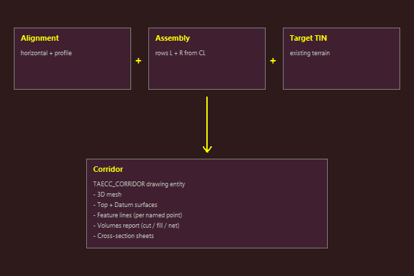
Three inputs (alignment, assembly, target TIN) combine into a single corridor entity that produces six output artifacts.
5.7.2. Assembly elements
Seven row types cover the building blocks of a typical road cross-section. Rows are added in order from the centerline outward on each side via the row-palette buttons in the Assembly Editor.
5.7.2.1. Lane
A drivable carriageway segment. Parameterised by width, cross-slope (superelevation-aware), and pavement depth. The pavement depth drives the datum surface — what sits under the road.
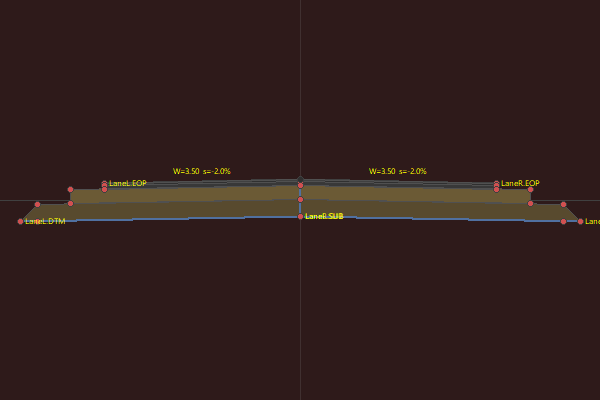
Lane element schematic.
Parameter |
Description |
|---|---|
Width |
Lane width in metres, measured from the parent point outward. |
CrossSlope |
Signed cross-slope as a decimal fraction. Negative means
falling away from CL. Receives the alignment’s superelevation
when |
PaveDepth |
(v1 legacy — migrated to a single course on load; use Courses…) Vertical pavement thickness in metres. In the current model the pavement is a course stack — see “Pavement structure — courses and materials” below. |
Peraltable |
When True, the cross-slope is overridden by the alignment’s SuperelevationLeft / SuperelevationRight value at each station. |
When to use it. Every road has at least one lane per direction. For divided roads, combine with a Median element between the opposing directions.
5.7.2.2. Shoulder
A narrower paved strip outboard of the outermost lane, typically sloped more steeply away from CL to shed water. Mechanically a narrower Lane with its own layer and label, named differently so quantities and feature lines distinguish it from the carriageway.
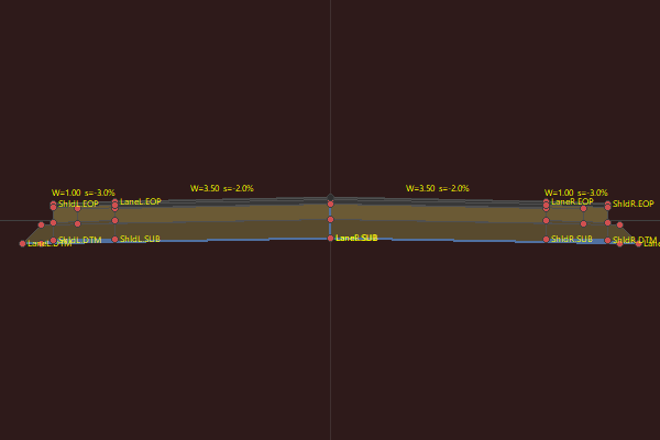
Shoulder element schematic (with parent Lane).
Parameter |
Description |
|---|---|
Width |
Shoulder width in metres. Typical 0.5–2.5 m depending on road class. |
CrossSlope |
Signed cross-slope, typically steeper than the lane (e.g. −3%). |
PaveDepth |
(v1 legacy — migrated to a single course on load; use Courses…) Pavement thickness, usually thinner than the lane (e.g. 0.05 m). |
Peraltable |
When True, follows the alignment’s superelevation. |
When to use it. Rural and highway designs almost always have shoulders. Urban designs typically use a Curb + Sidewalk instead.
5.7.2.3. Median
A divider strip at the centerline of a divided road, typically depressed below the running surface for drainage. Sits at the pivot.
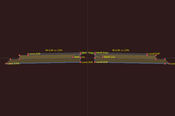
Median element schematic.
Parameter |
Description |
|---|---|
HalfWidth |
Half the total median width in metres (the full median is 2 × HalfWidth across both sides). |
Depth |
Vertical depression below the lane level in metres. |
InnerSlope |
Slope of the inner face of the median (V/H). |
When to use it. Divided highways and urban boulevards. Place the Median as the first row on each side so the lanes that follow sit on its outer edge.
5.7.2.4. Curb
An urban kerb — a stepped concrete profile separating the carriageway from the sidewalk. Three points define the profile: foot (at lane edge), top (raised), back (where the sidewalk begins).
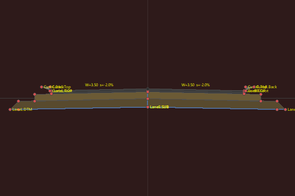
Curb element schematic (with parent Lane).
Parameter |
Description |
|---|---|
FaceW |
Horizontal width of the curb face in metres (typically 0.02–0.10 m). |
FaceH |
Vertical face height in metres (typically 0.10–0.20 m). |
TopW |
Top width in metres (the flat top of the kerb stone). |
When to use it. Urban streets with sidewalks. Combine with a Sidewalk row immediately after the Curb.
5.7.2.5. Sidewalk
A pedestrian walking surface outboard of the curb. Mechanically similar to a Lane (width + cross-slope + depth) but typically with gentler slopes and shallower pavement.
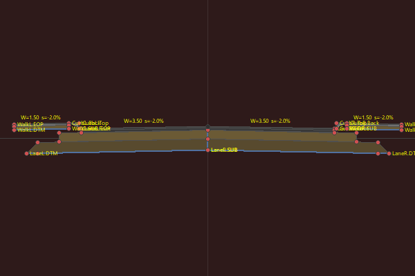
Sidewalk element schematic (with parent Lane + Curb).
Parameter |
Description |
|---|---|
Width |
Sidewalk width in metres. Typical 1.0–3.0 m. |
CrossSlope |
Drainage slope, typically gentle (e.g. −2%). |
PaveDepth |
(v1 legacy — migrated to a single course on load; use Courses…) Pavement thickness, typically shallow (e.g. 0.05 m). |
When to use it. Urban roads with pedestrian provision. Always follows a Curb.
5.7.2.6. Slope
The daylight chain — connects the outermost designed point to the existing-ground TIN. Walks at the cut slope until the TIN is reached if the design is above ground; walks at the fill slope if below ground.
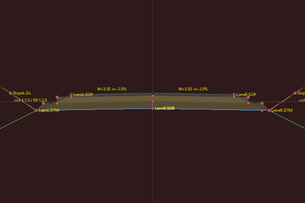
Slope element schematic showing cut and fill daylighting.
Parameter |
Description |
|---|---|
CutSlope |
Vertical-to-horizontal ratio for cut sections (design above ground).
E.g. |
FillSlope |
Vertical-to-horizontal ratio for fill sections (design below ground).
E.g. |
When to use it. The last element on each side of every assembly. Without it the corridor has no defined edge to the existing-ground.
5.7.2.7. Generic
An escape hatch for cross-section elements not covered by the catalogue. Specifies a raw (DX, DY) offset from the parent point. No automatic relationship to lanes, layers, or superelevation — exactly what you type is exactly what you get.
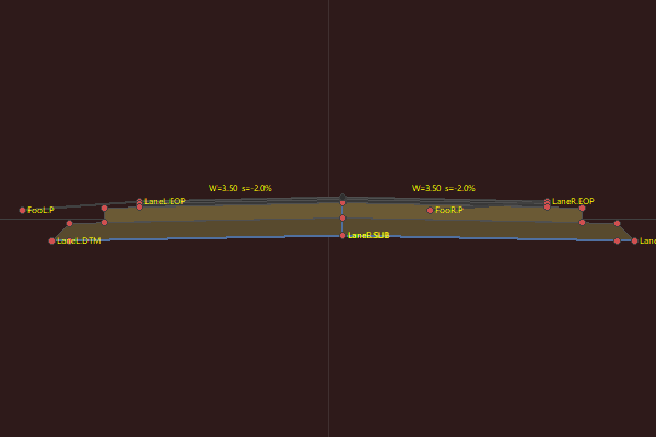
Generic element schematic — raw DX/DY offset.
Parameter |
Description |
|---|---|
DX |
Horizontal offset in metres from the parent point. Sign is absolute (not flipped by side), so author Left- and Right- side Generic rows with opposing signs if you want symmetry. |
DY |
Vertical offset in metres from the parent point. |
When to use it. Crash barriers, retaining walls, custom guardrails, ditches that don’t fit the Slope template, or any geometry the Lane/Shoulder/Curb/Median/Sidewalk vocabulary doesn’t capture.
5.7.3. Pavement structure — courses and materials
Lane, Shoulder, and Sidewalk rows no longer carry a single pavement thickness. Each carries a course stack: an ordered list of courses, where each course is a parametric shape (material + width + thickness + edge treatment) anchored to an earlier point in the assembly.
5.7.3.1. What a course is
A course has:
Material — a name from the drawing’s material library (below).
Width / Thickness — in metres; a Width of 0 inherits the parent row’s width.
Edge treatment (left and right independently) — Vertical (a plain rectangular edge) or Taper with a slope (dh/dv), which widens the course’s bottom edge outward, producing a benched or stepped course boundary.
Anchor — a 9-point attachment: SelfPt (the course’s own corner) glued to TargetPt (a named point of an earlier structure), plus a DX/DY offset. The nine anchor points are the corners and edge midpoints of the course’s rectangle:
TL /
TC / TR / ML / MC / MR / BL / BC / BR
(top/middle/bottom × left/centre/right).
5.7.3.2. Chain default
Leave Target blank and a course anchors to the chain default:
the first course (index 0) hangs from the row’s top link (TL);
course k hangs under course k − 1’s bottom-left corner
(TL → BL). This is exactly the historical single-PaveDepth
behaviour — templates only need explicit anchors where they deviate
from a straight-down stack.
5.7.3.3. Wider / centered courses
A base or subbase course usually needs to be wider than the layer
above it. To centre the extra width on both sides, set SelfPt =
TC and TargetPt = BC (top-centre onto bottom-centre) together
with a Width greater than the row width: the course centres
itself under the course above and steps out evenly on both sides.
The shipped Base course instead widens outward only (see below):
it keeps the default anchor, so its inner edge stays pinned directly
under the course above (and ultimately under the row’s own inner
anchor) while the full extra width goes on the outer edge
(width = W + 0.6).
5.7.3.4. Taper feet
Set an edge to Taper with a slope to get a widening foot instead
of a vertical step — typical for a subbase course that needs to bear
on undisturbed ground beyond the layers above it. The shipped
Subbase course uses Taper 1:1 on its outer edge only — the inner
edge stays vertical, pinned at the row’s own inner anchor — with
width = W + 1.2.
5.7.3.5. Cross-row anchoring
A course’s Target field can name another row’s structure, not
just “the course above” — e.g. a drainage course anchored to
LaneL.Subbase.BR ties its self point to the bottom-right corner
of the left lane’s subbase course, letting one row’s stack key off
another row’s. Anchoring to a structure that hasn’t been built yet
(a forward reference, or a cycle) fails the build with a console
error naming the unresolved target instead of crashing — fix the
name and rebuild.
5.7.3.6. Drawing-level material library
Every drawing has its own material library (independent of the assembly library), opened with the Materials… button in the Assembly Editor header. It comes seeded with seven defaults:
Asphalt Wearing
Asphalt Binder
Asphalt Base
Base (crushed stone)
Subbase
Concrete
Drainage gravel
Each material is a name plus a display colour; add, delete, or recolour entries freely, and reference any of them from any course’s Material field.
5.7.3.7. The datum: bottom of the last course
The corridor’s datum surface follows the outer bottom corners of a row’s LAST course — not whichever course happens to be geometrically deepest. Because custom anchors (cross-row targets, DX/DY offsets) mean the true deepest bottom isn’t knowable until the whole stack resolves, the rule is simply “the deepest course goes last”; every shipped template already follows it (subbase is always the final course). Curb, Median, and Generic rows still advance the datum chain the way they always did (to their Back / Edge / offset point). A row with no courses (a “zero-course” row — see below) advances the datum from its own top link only.
5.7.3.8. Quantities: per-material volumes + excavation-to-formation
BUILDCORRIDOR now prints, after the usual cut/fill/net line:
Excavation (to formation) — the volume between existing ground and the datum surface where ground sits above datum, i.e. what actually has to be dug to reach subgrade. This is distinct from the ground-vs-top cut/fill figure, which ignores everything below the finished road surface.
A material table, one row per material referenced anywhere in the assembly, each the integrated volume of every course tagged with that material along the whole corridor.
5.7.3.9. Known v1 simplifications
Two shortcuts are accepted in this phase and may be refined later. (The 2026-07-22 final review corrected both this section and the shipped templates themselves — see below; the previously-published “roughly 0.075 m²” figure was wrong on top of describing the wrong joint, by about 8x.)
CL/median joint — none. Base and Subbase widen outward only from each row’s own inner anchor (never back past CL or a median edge), so on a single-lane side (Rural, Rural-Narrow, Urban) the two lanes’ courses meet exactly at the shared edge with zero overlap.
Adjacent-lane stack overlap (multi-lane sides only). On a multi-lane side (Urban-Boulevard, Highway, Freeway) each lane’s Base/Subbase still widens outward past its own outer edge into the footprint of the next lane, whose own courses start fresh from its own inner edge and never reach back — so the same kind of double count still happens, just at the internal lane-to-lane joint instead of at CL. For the shipped stacks: Base overlaps 0.6 m × 0.25 m = 0.15 m², Subbase overlaps 1.5 m (1.2 m rectangle + 0.3 m taper foot) × 0.30 m = 0.45 m², roughly 0.6 m² of cross-section per internal lane-to-lane joint (every shipped multi-lane template’s lane width exceeds the 1.5 m Subbase reach, so this figure is exact, not capped by a narrower neighbour).
Shoulder interface. The same outward reach also overlaps a Lane’s own following Shoulder — capped by the shoulder’s width where that is narrower than the 0.6 m/1.5 m reach (e.g. Rural-2x3.5’s 1.0 m-wide shoulder caps the Subbase overlap at 1.0 m × 0.30 m = 0.30 m² rather than the full 0.45 m²) — on top of the pre-existing small thickness step where the shoulder’s own Wearing course meets the lane’s Binder course rather than tying in continuously. A fully continuous tie-in is possible today via cross-row anchors but the shipped templates don’t yet author it — planned template work for a later phase.
5.7.3.10. Zero-course rows
A pavement row (lane/shoulder/sidewalk) with an empty course array is a legal “zero-course” row: for datum purposes it behaves like a bare top-only row — only its top link is emitted, no separate datum point is paired to it, and the next row’s stack continues from that top link exactly as before courses existed. This is also the shape a lane/shoulder/sidewalk row takes if you delete every row in its Courses… dialog.
5.7.4. Section styles
Corridor cross-sections — both model-space section views
(TAECC_SECTIONVIEW) and the section sheets generated for plotting
(TAECC_SECTIONSHEET) — draw their appearance from a named
corridor section style. A style is a single named record that
controls material fills (solid colour or hatch), per-element outline
colours, the corridor silhouette pen, the background/grid, cut/fill
shading, and four independent annotation toggles. Styles live in a
library on the drawing, exactly like the alignment, surface, and
profile-view style libraries; a view or sheet picks one by name, and a
blank name — or a name that no longer exists in the library — falls
back to Standard.
Geometry (extents, datum/top elevation, vertical exaggeration, title) stays on the view/sheet itself; the style only ever controls how that geometry is drawn.
5.7.4.1. Built-in styles
Every drawing’s corridor section style library ships with two built-in styles that cannot be renamed or deleted:
Style |
Description |
|---|---|
Standard |
Solid material fills using each material’s colour from the drawing’s material library (the same colours seen in the Assembly Editor preview), grey course outlines, and a yellow dash-dot corridor silhouette. |
Monochrome |
Plot-ready: white background, black pens throughout (grid, ground, outlines, silhouette), cut/fill shading turned off, and all seven default materials filled with a black ANSI31 hatch (alternating 0°/90° angle material-to-material) instead of a solid colour. |
Both built-ins, and any custom style you add, are available to every section view and sheet in the drawing.
5.7.4.2. Opening the Style Editor
Civil › Style Manager, then select Section View Styles in the left-hand category tree. The editor embeds in the manager’s right pane: a left list strip of every style in the library — New, Duplicate, Rename, Delete buttons below it (Standard is protected from rename and delete) — and a tabbed panel on the right with five tabs: View, Ground, Corridor, Annotations, Preview.
5.7.4.3. Editable fields
Field |
Meaning |
|---|---|
Show grid |
Toggles the background grid. |
Background / grid / minor-grid colour |
Colours for the view background and the major/minor grid lines. |
Major/minor grid X/Y |
Grid line spacing, horizontal and vertical, in drawing units. |
Axis text height |
Pixel height of the offset/elevation axis labels. |
Field |
Meaning |
|---|---|
Ground pen colour / width |
Pen for the existing-ground surface polyline(s). |
Show cut/fill shading |
Toggles the tinted region between existing ground and the corridor’s top surface. |
Cut colour / Fill colour |
Shading colours for the cut region (ground above design) and the fill region (ground below design). |
Field |
Meaning |
|---|---|
Show material fills |
Master toggle for every course-shape fill (solid or hatch). |
Overrides grid |
Per-material fill overrides — see “Material fills and overrides” below. |
Outline colours (7) |
One colour per row kind — Lane, Shoulder, Median, Curb, Sidewalk, Slope, Generic — for the course-shape outlines of that kind. |
Silhouette colour / width / style |
Pen for the corridor’s outer silhouette (Top left-to-right, Datum right-to-left) — the single yellow dash-dot line sections drew before this feature shipped. |
Course-line colour |
Reserved colour field for course-boundary lines; the shipped renderer currently draws course boundaries through the outline pens above. |
Field |
Meaning |
|---|---|
Show slope/width labels |
|
Show point marks / Show point names |
Marker + name for every named corridor point ( |
Show area block |
Per-station cut/fill/excavation-to-formation figures plus a per-material area table, drawn beside the section. |
Show legend / Legend per sheet |
Material-color legend box; per sheet draws one legend for the whole sheet instead of one per section cell. |
Annotation text height |
Pixel height shared by every annotation label. |
The Preview tab paints a small synthetic section (two course shapes plus a ground polyline) through the same renderer used for real section views and sheets, so every field change is visible immediately without building a corridor.
5.7.4.4. Material fills and overrides
Every course shape resolves its fill in this order:
Override — if the style has a row for the shape’s material in the Corridor tab’s overrides grid, that row wins: Mode (typed as
solidorhatch), and forhatcha Pattern name (e.g.ANSI31, any pattern from the drawing’s hatch-pattern library), Scale, Angle, and Colour.Material colour — otherwise, the shape fills solid with its material’s colour from the drawing’s material library (the same library the Assembly Editor’s Materials… button opens).
Row-kind fallback — untagged shapes (curbs, medians — see “Pavement structure” above) fall back to a colour keyed by row kind.
This is the same resolution the Assembly Editor’s schematic preview uses (see “Editor display” below), so a material recoloured via Materials… updates consistently everywhere: assembly preview, thumbnails, section views, and section sheets.
Add or remove override rows with the grid’s Add/Delete buttons; each row is independent, so a style can hatch-fill some materials while leaving others solid.
5.7.4.5. Persistence
The style library is saved into the drawing (IQML/IQZ) under a
CorridorSectionStyles element, alongside the other civil style
libraries. Section views and sheets store only the style name;
resolution to a concrete style happens at draw time, so a missing or
deleted style name falls back to Standard without invalidating the
view or sheet. Because assemblies and corridor sections were not
previously released, there is no legacy-drawing migration concern —
every existing view/sheet simply resolves as Standard.
Note
The Create Section Sheet… dialog’s Settings tab now includes a Section style combo (defaulting to Standard) so a new sheet can be assigned any style, including Monochrome, at creation time. There is still no per-entity control to switch an existing view or sheet to a different style after the fact — use the Preview tab above to check how any style will render before that control ships in a later phase.
5.7.5. Conditional rows, ditches and benching
(Corridor v1.3 Phase 5.) Three additions let an assembly’s daylight side adapt to the ground it actually meets, instead of always resolving the same geometry: a per-row Cut/Fill condition, a trapezoidal Ditch row for the cut side, and benching — tall daylights broken into repeated lift-and-bench steps rather than one long slope face. A related geometry fix ships alongside them: the daylight hinge now springs from the true edge of excavation on both branches (see “The excavation-edge hinge fix” below).
5.7.5.1. Row condition: Always / Cut / Fill
Every row in the Assembly Editor grid now carries a Cond column (inserted right after Name), a three-way choice: blank/Always (the row is unconditional — today’s behaviour, and the default for every existing row), Cut, or Fill. A row set to Cut or Fill only contributes its geometry, area, and section-view shapes at stations where the corridor resolver decides that side of the alignment is actually in cut (respectively fill) — at every other station the row emits nothing at all, as if it had never been authored.
The decision is made once per side per station, at the daylight hinge (the point described in the hinge fix below): the resolver probes the target surface directly above/below the hinge — ground higher than the hinge means the station is in cut on that side, otherwise it’s in fill — then activates every Cut-conditioned row and deactivates every Fill-conditioned row, or vice-versa. The losing branch is not merely hidden: it contributes zero to cut/fill/ excavation quantities, and its shapes never reach the section views or section sheets, exactly as if it were pruned from the assembly for that station.
In the Assembly Editor’s live preview, conditional geometry is drawn schematically on both branches at once so you can review each side’s design without building a corridor: the cut branch dashed and tinted orange, the fill branch dashed and tinted green. Only one branch will actually resolve at any given corridor station, but the preview always shows both so a conditional ditch or bench setup can be checked without needing test ground.
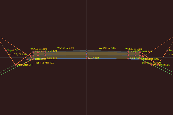
A cut-only Ditch row (orange, dashed) ahead of the daylight.
5.7.5.2. Ditch
Ditch is a new row kind for a trapezoidal drainage channel, added
with the +Ditch button under each side’s row grid (next to the
other row-palette buttons). A new ditch row defaults to name
Ditch, layer C-DTCH, and condition Cut — it is meant for
the cut branch and is authored that way by default, though any
condition is legal if you have an unusual use for it.
Parameter |
Description |
|---|---|
Depth |
Vertical depth of the ditch invert below the point it springs from, in metres. |
BottomWidth |
Width of the ditch’s flat invert in metres. 0 produces a V-ditch (no flat bottom, the two slopes meet at a point). |
ForeSlope |
Slope of the near (inboard) face, as 1:n (rise:run — e.g.
|
BackSlope |
Slope of the far (outboard) face, as 1:n. Edited in the row params dialog (double-click any P column of a Ditch row) rather than the grid, alongside Depth/BottomWidth/ForeSlope. |
A ditch springs from the excavation edge exactly like an unconditional daylight would, then walks down at ForeSlope to the invert, across BottomWidth, and back up at BackSlope — and it is that rising backslope which becomes the starting slope of the cut daylight chain that follows it, so the ditch and the cut face read as one continuous excavated profile rather than two unrelated elements. The ditch’s own bottom also extends the excavation envelope: quantities’ Excavation (to formation) figure counts everything down to the ditch invert on an active ditch, not just to the pavement datum, since a ditch is simultaneously a finished-surface feature (it’s what you see) and a formation feature (it’s what has to be dug). A ditch row draws as an open outline (no fill) using its own outline-colour slot in the section style’s Corridor tab, alongside Lane/Shoulder/Median/ Curb/Sidewalk/Slope/Generic.
5.7.5.3. Benching
Tall daylights no longer walk a single uninterrupted slope face all the way to the ground: a Slope row can now specify benching separately for its cut branch and its fill branch, each a triple of MaxHeight / BenchWidth / BenchSlope edited in the row params dialog (double-click a Slope row’s P column). Leaving MaxHeight at its default of 0 disables benching for that branch — the daylight behaves exactly as before.
With benching enabled, the resolver walks the active branch’s slope
for at most MaxHeight of vertical rise/fall; if the ground
crossing is found inside that lift, the ordinary daylight point closes
the chain there (to the usual 1 mm tolerance) and benching never
engages for that station. If the ground is not yet reached, the
daylight instead breaks outward: a bench point at the lift’s top,
walking BenchWidth outward at BenchSlope to a second bench
point, then the next lift starts from there. Named points appear
along the way — DL.B1, DL.B1E, DL.B2, DL.B2E, … — one
pair per completed lift, so section views and feature lines carry a
distinct point per bench. Lifts repeat until the ground is met; a
hard cap of 20 lifts stops the walk and flags that station
Ungraded on the command line rather than looping forever on
pathological ground.
The Assembly Editor’s preview draws one schematic bench break — a single jog partway along the branch’s daylight stub — whenever a branch’s MaxHeight is non-zero, as a reminder that benching is active; the preview’s flat test ground can’t show a real multi-lift walk, so the schematic jog is deliberately just an indicator, not a solved bench chain.
5.7.5.4. The excavation-edge hinge fix
Both the cut and the fill daylight now spring from the end of excavation — the outer bottom corner of a side’s outermost course stack, exactly where the excavation-to-formation envelope actually ends — rather than from the shoulder’s finished top edge as before. Previously the daylight point anchored to the row chain’s top link, which sits above and inboard of a widened subbase or a taper foot; because those courses are authored wider than the row itself (see “Pavement structure” above), the true excavated face reached further out than the daylight line implied, undercutting it. Anchoring to the excavation edge instead means the daylight — and any ditch feeding into it — starts exactly where the dig actually stops.
A short connector link closes the gap down the outermost course stack’s outer face (from the row’s top point to the excavation-edge point) so the Top chain stays continuous for area and silhouette purposes; on a side with no course stacks at all (e.g. a bare Generic or Median row feeding straight into a Slope), there is no excavation edge to speak of and the daylight falls back to anchoring at the row’s own top point, exactly as before this fix.
This is a bug fix, not a new option — every assembly with course stacks on its outer rows sees its daylight (and, if you add one, its ditch) start slightly further out and down than in earlier releases; unconditional daylight-only assemblies otherwise resolve bit-identical geometry.
5.7.5.5. Upgraded standard templates
All six templates in standard-roads.iqal (Rural-Narrow-2x3.0,
Rural-2x3.5, Urban-2x3.5+walks, Urban-Boulevard-2x2x3.25,
Highway-2x2x3.5+median, Freeway-2x3x3.75) now carry, on each side,
immediately before the closing Slope row:
A Cut-only ditch — Depth 0.5 m, BottomWidth 0.5 m, ForeSlope 1:2, BackSlope 1:1.5.
Benching on both branches of the Slope row — 5 m lifts, 1.5 m benches, 4% bench slope.
Note
On Urban-2x3.5+walks and Urban-Boulevard-2x2x3.25 the ditch ends up sitting behind the sidewalk (Lane → Curb → Sidewalk → Ditch → Slope) — a cut-drainage ditch with no shoulder buffer ahead of it, which is unusual civil practice for an urban street. This is a literal application of “the ditch goes between the last row and the slope on each side” to templates that have no shoulder; the other four templates place the ditch after a shoulder, which reads normally. Review this per project: edit the ditch’s parameters, move it, or delete the row entirely on a copy of these two templates if a project doesn’t want cut drainage immediately behind its pedestrian walk.
5.7.5.6. Persistence
Row condition, ditch parameters, and both branches’ bench parameters
round-trip through .iqal (and the equivalent IQML) exactly like
every other row field: an unconditional row omits the condition
attribute entirely (so pre-Phase-5 files still load with every row
defaulting to Always), a Ditch row always writes its four ditch
attributes, and a Slope row writes each of its six bench attributes
only when non-zero. This is an additive extension of the existing v2
schema — no version bump was needed.
5.7.6. Standard sample library
IQcad ships six pre-authored road templates in
standard-roads.iqal (under testdata/library/ in the
distribution). An empty drawing’s assembly library auto-loads them
the first time you open Civil › Assemblies… or run
BUILDCORRIDOR — no manual import step is needed. You can also
seed them on demand with SAMPLEASSEMBLIES (alias SAS), which
is idempotent: assemblies that already exist by name are skipped.
The Import button in the Assembly Editor remains available for
loading additional/custom .iqal files from elsewhere.
5.7.6.1. Rural-Narrow-2x3.0
Low-traffic backroad. Narrow lanes and shoulders with relatively steep slopes — appropriate for mountain roads, forest tracks, and single-family rural access.
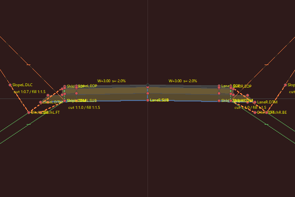
Rural-Narrow-2x3.0 cross-section.
When to use it. Low-volume rural backroads where right-of-way is constrained and design speed is low (under 50 km/h).
Composition (per side; right side is mirrored):
Order |
Element |
Parameters |
|---|---|---|
1 |
Lane |
Width 3.0 m, CrossSlope −2%, peraltable. Courses: Wearing 4 cm AC + Binder 6 cm AC + Base 25 cm (W+0.6 m, stepped) + Subbase 30 cm (W+1.2 m, taper 1:1). |
2 |
Shoulder |
Width 0.5 m, CrossSlope −3%, peraltable. Courses: Wearing 5 cm AC + Base 25 cm + Subbase 30 cm. |
3 |
Slope |
Cut 1:1, Fill 1:1.5 |
5.7.6.2. Rural-2x3.5
Standard symmetric two-lane rural road. 3.5 m lanes with 1.0 m shoulders and 1:1.5 cut / 1:2.0 fill slopes daylighting to the TIN.
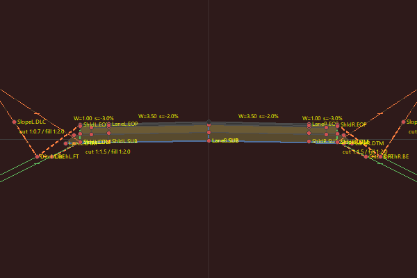
Rural-2x3.5 cross-section.
When to use it. Most rural and inter-urban roads outside settlements. The slopes assume typical engineering soils; for rock cuts use a steeper Slope row, for soft soils a gentler one.
Composition (per side; right side is mirrored):
Order |
Element |
Parameters |
|---|---|---|
1 |
Lane |
Width 3.5 m, CrossSlope −2%, peraltable. Courses: Wearing 4 cm AC + Binder 6 cm AC + Base 25 cm (W+0.6 m, stepped) + Subbase 30 cm (W+1.2 m, taper 1:1). |
2 |
Shoulder |
Width 1.0 m, CrossSlope −3%, peraltable. Courses: Wearing 5 cm AC + Base 25 cm + Subbase 30 cm. |
3 |
Slope |
Cut 1:1.5, Fill 1:2.0 |
5.7.6.3. Urban-2x3.5+walks
Urban street with kerb and sidewalk on each side. 3.5 m lanes, 0.15 m face-height kerb, 1.5 m sidewalk. No shoulder.
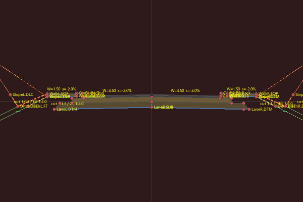
Urban-2x3.5+walks cross-section.
When to use it. Urban single-carriageway streets with pedestrian provision — the typical “residential collector” cross-section.
Composition (per side; right side is mirrored):
Order |
Element |
Parameters |
|---|---|---|
1 |
Lane |
Width 3.5 m, CrossSlope −2%, peraltable. Courses: Wearing 4 cm AC + Binder 6 cm AC + Base 25 cm (W+0.6 m, stepped) + Subbase 30 cm (W+1.2 m, taper 1:1). |
2 |
Curb |
FaceW 0.05 m, FaceH 0.15 m, TopW 0.30 m |
3 |
Sidewalk |
Width 1.5 m, CrossSlope −2%. Courses: Slab 5 cm concrete + Base 10 cm. |
4 |
Slope |
Cut 1:1.5, Fill 1:2.0 |
5.7.6.4. Urban-Boulevard-2x2x3.25
Divided urban with central median and sidewalks. Two 3.25 m lanes per direction, narrow planted median, kerb and 2.0 m sidewalk.
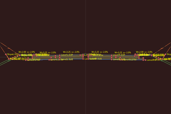
Urban-Boulevard-2x2x3.25 cross-section.
When to use it. Urban arterials with pedestrian provision and traffic separation — typical “city boulevard” cross-section.
Composition (per side; right side is mirrored):
Order |
Element |
Parameters |
|---|---|---|
1 |
Median |
HalfWidth 0.75 m, Depth 0.10 m, InnerSlope 1:10 |
2 |
Lane (Lane1) |
Width 3.25 m, CrossSlope −2%, peraltable. Courses: Wearing 4 cm AC + Binder 6 cm AC + Base 25 cm (W+0.6 m, stepped) + Subbase 30 cm (W+1.2 m, taper 1:1). |
3 |
Lane (Lane2) |
Width 3.25 m, CrossSlope −2%, peraltable. Courses: Wearing 4 cm AC + Binder 6 cm AC + Base 25 cm (W+0.6 m, stepped) + Subbase 30 cm (W+1.2 m, taper 1:1). |
4 |
Curb |
FaceW 0.05 m, FaceH 0.15 m, TopW 0.30 m |
5 |
Sidewalk |
Width 2.0 m, CrossSlope −2%. Courses: Slab 5 cm concrete + Base 10 cm. |
6 |
Slope |
Cut 1:1.5, Fill 1:2.0 |
5.7.6.5. Highway-2x2x3.5+median
Divided rural highway. Two 3.5 m lanes per direction, 2.5 m shoulders, 1.0 m central median.
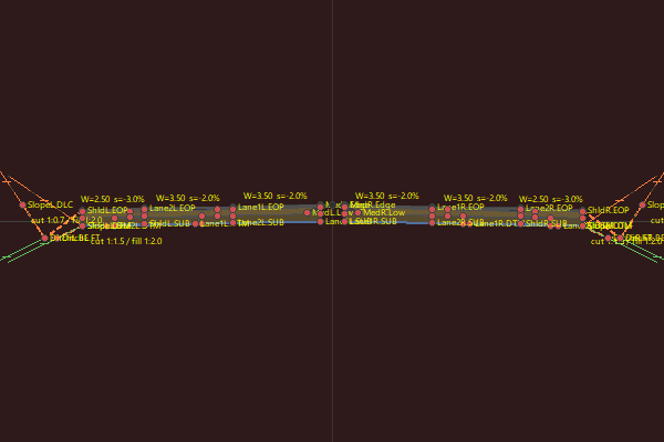
Highway-2x2x3.5+median cross-section.
When to use it. Inter-city divided highways with moderate traffic. Wider median templates can be authored by adjusting HalfWidth on the Median row.
Composition (per side; right side is mirrored):
Order |
Element |
Parameters |
|---|---|---|
1 |
Median |
HalfWidth 1.0 m, Depth 0.30 m, InnerSlope 1:10 |
2 |
Lane (Lane1) |
Width 3.5 m, CrossSlope −2%, peraltable. Courses: Wearing 4 cm AC + Binder 6 cm AC + Base 25 cm (W+0.6 m, stepped) + Subbase 30 cm (W+1.2 m, taper 1:1). |
3 |
Lane (Lane2) |
Width 3.5 m, CrossSlope −2%, peraltable. Courses: Wearing 4 cm AC + Binder 6 cm AC + Base 25 cm (W+0.6 m, stepped) + Subbase 30 cm (W+1.2 m, taper 1:1). |
4 |
Shoulder |
Width 2.5 m, CrossSlope −3%, peraltable. Courses: Wearing 5 cm AC + Base 25 cm + Subbase 30 cm. |
5 |
Slope |
Cut 1:1.5, Fill 1:2.0 |
5.7.6.6. Freeway-2x3x3.75
Three-lane freeway per direction. 3.75 m lanes, 3.0 m shoulders, wider 2.0 m median.
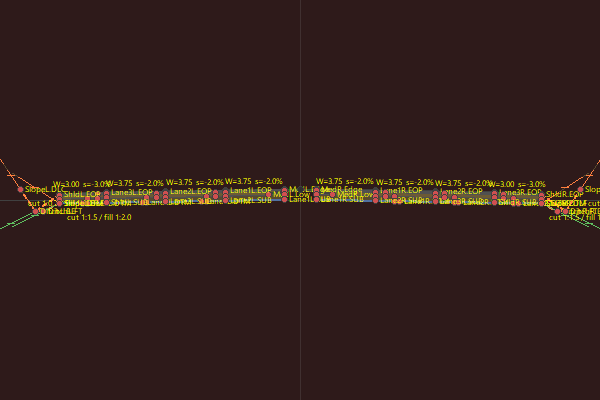
Freeway-2x3x3.75 cross-section.
When to use it. High-volume motorways and freeways. For four+ lanes per direction, copy and add additional Lane rows.
Composition (per side; right side is mirrored):
Order |
Element |
Parameters |
|---|---|---|
1 |
Median |
HalfWidth 2.0 m, Depth 0.30 m, InnerSlope 1:10 |
2 |
Lane (Lane1) |
Width 3.75 m, CrossSlope −2%, peraltable. Courses: Wearing 4 cm AC + Binder 6 cm AC + Base 25 cm (W+0.6 m, stepped) + Subbase 30 cm (W+1.2 m, taper 1:1). |
3 |
Lane (Lane2) |
Width 3.75 m, CrossSlope −2%, peraltable. Courses: Wearing 4 cm AC + Binder 6 cm AC + Base 25 cm (W+0.6 m, stepped) + Subbase 30 cm (W+1.2 m, taper 1:1). |
4 |
Lane (Lane3) |
Width 3.75 m, CrossSlope −2%, peraltable. Courses: Wearing 4 cm AC + Binder 6 cm AC + Base 25 cm (W+0.6 m, stepped) + Subbase 30 cm (W+1.2 m, taper 1:1). |
5 |
Shoulder |
Width 3.0 m, CrossSlope −3%, peraltable. Courses: Wearing 5 cm AC + Base 25 cm + Subbase 30 cm. |
6 |
Slope |
Cut 1:1.5, Fill 1:2.0 |
5.7.7. Editor display
The Assembly Editor’s live preview and assembly picker read like a real cross-section rather than a wireframe — the shipped fills use the same colors seen in the Rural-2x3.5 figure above.
5.7.7.1. Filled parts
Every course shape fills with its material’s color from the drawing’s material library: recolor a material via Materials… and the preview and every thumbnail follow immediately. Curbs and medians carry no material reference yet, so they fill with fixed fallback colors (concrete-grey and green respectively). Course outlines draw as thin grey lines over the fills; the Top and Datum lines keep their existing (thicker, colored) styling.
5.7.7.2. Annotations
Lane, shoulder, and sidewalk rows show W=<width> s=<slope>% above
their top link; daylight points show their cut 1:n / fill 1:n
ratios. Labels declutter automatically — a link drawn narrower than
40 px on screen hides its label; zoom in to bring it back.
5.7.7.3. Both daylight branches
At the daylight hinge the preview always draws both a schematic cut branch (dashed, rising) and a schematic fill branch (solid, falling), each 3 m long, in addition to the branch actually resolved against the flat preview ground, which keeps its normal link styling.
5.7.7.4. Thumbnail list
The assembly picker is a list of thumbnail + name rows to the left of the preview, replacing the old name combo. Selecting a row loads that assembly into the left/right grids. Thumbnails refresh automatically on Apply, Import, Rename, and Delete, and after material color edits.
5.7.7.5. Course highlighting
While the Courses… dialog is open, selecting a row outlines the corresponding course in cyan in the preview behind the dialog. On some systems the outline also updates live while the dialog is open; on every system the highlighted course remains visible after you close the dialog, until the next edit action (Apply, switching the selected assembly, or adding, deleting, moving, or mirroring a row) clears it.
5.7.8. Building a corridor
Once you have an alignment, a vertical profile, and an existing-ground surface in the drawing, building a corridor takes four steps.
- 1. Open the Assembly Editor.
Civil → Assemblies…opens the editor. In an empty drawing the six standard road templates auto-load — the combo already lists them, no import needed. Use Import only to bring in additional or custom.iqalfiles from elsewhere.- 2. (Optional) Author your own assembly.
Click New, give it a name, then click the row-palette buttons (+Lane, +Shoulder, etc.) under the left grid to add rows in order from CL outward. Click Mirror to copy the left side to the right. The live preview updates as you type. Click OK to save into the drawing.
For lane/shoulder/sidewalk rows, the Courses… button (one per side, next to the row grid) opens a modal grid listing every course in the row’s stack — columns
#,Name,Material,Thickness,Width,SelfPt,Target,TargetPt,EdgeL,SlopeL,EdgeR,SlopeR,DX,DY— with Add / Delete / Up / Down buttons to manage rows and a Material combo populated from the drawing’s material library. Click OK in the courses dialog to write the stack back, then OK/Apply in the assembly editor to commit it.The editor header’s Materials… button opens the drawing-level material library: a name + colour grid with Add / Delete and a colour-picker button that recolours the selected row. Changes apply immediately to every course referencing that material’s name.
- 3. Bind the corridor to an alignment.
Open the Alignment PI Editor, select your alignment, switch to the Corridor tab. Pick the assembly + target surface, set the sample frequency (default 5 m).
- 4. Build.
Click Build Corridor (or run
BUILDCORRIDORfrom the command line, aliasBC). Within a few seconds the drawing gains:A 3D mesh of the corridor body.
A Top surface (AECC_SURFACE) draping the road’s running surface.
A Datum surface (AECC_SURFACE) under the pavement.
One 3D feature line per named point along the alignment (edge of pavement, daylight line, etc.).
A volumes report on the command line: cut, fill, net, excavation-to-formation, and a per-material quantity table (see “Pavement structure — courses and materials” above).
If the status label reads Out of date, you have edited a source (alignment, target surface, or library); click Build again to regenerate the outputs.