5.1. Civil Toolspace and Settings
Civil tools extend the standard CAD objects with survey-specific capabilities. They are accessible from the Civil menu, the Civil ribbon tab, and the Civil Toolspace panel.
5.1.1. Civil Toolspace
Toggle the panel with Civil › Civil Toolspace. The panel shows a tree with four top-level branches:
▼ Survey Points  (N)
    ▼ _All Points  (N)
        └ #1   N=538345.123   E=4872341.456   Z=412.5   BM-001
        └ #2   …
    ▼ GroupA  (3)
        └ #1   …
▼ Tunnel Section Lines  (N)
    └ Measured-1  (43 pts)
▼ Surfaces  (1)
    ▼ Terrain
        ▼ Definition
            └ Point Groups
            └ Boundaries
        ▼ Contours
            └ Major @ 5.0
            └ Minor @ 1.0
▼ Alignments  (1)
    └ Alignment_1  (L=350.00  PIs=5)
Click the Refresh button (top-right of the panel header) to rebuild the tree after bulk operations.
Double-click a leaf node to select that object in the canvas and zoom to it.
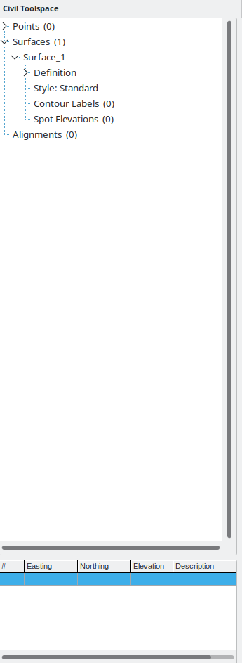
The Civil Toolspace panel with survey points, surfaces, and alignments.
5.1.2. Civil Settings
Open with Civil › Civil Settings… to configure per-drawing civil engineering parameters. All settings are saved inside the IQML file and restored when the drawing is reopened.
The dialog has six tabs.
5.1.2.1. Units & Zone
Setting |
Description |
|---|---|
Linear Unit |
Choose Meters, Feet, or US Survey Feet. |
Drawing Scale |
Numeric scale denominator — e.g. enter |
Coordinate System |
Browse by category or search by name/code from ~182 built-in EPSG systems. The detail panel shows the EPSG code, datum, projection method, and linear unit. |
5.1.2.2. Transformation
Setting |
Description |
|---|---|
Enable Transformation |
Check to activate coordinate transformation for the drawing. |
Reference Easting (X) |
X coordinate of the reference (base) point. |
Reference Northing (Y) |
Y coordinate of the reference (base) point. |
Rotation |
Rotation angle in degrees. |
Scale Factor |
Multiplicative scale factor (default |
5.1.2.3. Ambient Settings
Setting |
Description |
|---|---|
Precision |
Number of decimal places (0–8) for distance, elevation, coordinate, angle, grade, and slope values. |
Angle Format |
Choose Degrees, DMS (degrees-minutes-seconds), Grads, or Radians. |
Direction Format |
Choose Bearing, South Azimuth, or North Azimuth. |
5.1.2.4. Abbreviations
Standard abbreviations used in labels and reports:
Abbreviation |
Default value |
|---|---|
Station |
|
Right |
|
Left |
|
North / South / East / West |
|
Elevation |
|
Grade Break |
|
Click Reset to Defaults to restore the factory abbreviation values.
5.1.2.5. Layers
The Layers tab controls the Civil 3D-style layers that civil objects create for their components (see Civil Object Layer Defaults for the full list).
Enable civil object layers turns the automatic layers on or off.
Layer prefix is the leading group code,
Cby default.Include object name in layer inserts the object’s name between the group and the suffix, e.g.
C-ROAD-Alignment_1-PI.
The grid lists every object component with its Group, Suffix, the resulting Layer pattern and the layer Colour. Type in the Group and Suffix cells to rename a layer; click the colour swatch to choose a new colour. The Layer column updates as you type. Reset Layers restores the built-in names and colours for the whole grid.
The changes apply to layers created from then on. A layer that already exists in the drawing keeps its name and colour; rename or recolour it in the Layer Manager.
5.1.2.6. Draw Order
The Civil Settings dialog includes a Draw Order tab that controls the rendering priority of civil objects.
Inter-object type priority determines the order in which different civil object categories are drawn. The default order (back to front) is:
Surfaces
Parcels
Alignments
Points
Drag items in the list to reorder them. Objects drawn later appear on top.
Intra-surface sub-element ordering controls the draw order of components within a single surface (e.g. triangles before contours, contours before labels). This is configured per-surface in the Surface Style Editor on the Draw Order tab.
Dialog buttons:
OK — applies all changes.
Cancel — discards all changes.
Reset All — restores every setting across all tabs to its default value.
5.1.3. Elevation Band Legend
When a surface uses the Elevation Banding style (or any style with elevation bands enabled), an on-canvas legend can be displayed showing stacked color boxes with the corresponding elevation ranges.
Enable or disable the legend per-style using the ShowLegend toggle in the Elevation Bands tab of the Surface Style Editor. The legend is rendered as a GL overlay and updates automatically when the surface elevation range or band configuration changes.