3.11. Format Settings
All format dialogs are under the Format menu.
3.11.1. Layers
Format › Layers… opens the standalone Layers Manager form. See Layers, Linetypes and Text Styles for full details.
3.11.2. Linetypes
Format › Linetypes… opens the standalone Linetypes Manager form.
Displays all loaded linetypes with name, description, pattern preview, source,
and complex flag. Toolbar buttons: Load from File… (import .LIN files),
Assign to Current Layer and Library (add the program’s library linetypes
that the drawing lacks).
3.11.3. Drawing Variables
Format › Variables Editor… (or the Draw Vars ribbon button) opens the Drawing Variables form showing all per-drawing settings in a two-column grid. Units and precision have their own dialog under Format › Units….
3.11.4. Point Style (Ctrl+Shift+D)
Opens the Point Style Editor — a 4 × 5 grid of 19 marker shapes. Click a cell to select the active global marker shape, and set the display size in the Size field below the grid.
The named Point Style Library stores per-style settings that can be
assigned to individual AEC Survey Points via the PointStyleName property.
Built-in style |
Default marker |
|---|---|
Standard |
Cross (+) |
Benchmark |
Triangle with dot |
Control Point |
Circle with cross |
GPS Rover |
Square with dot |
Iron Rod |
Circle with vertical bar |
Additional styles can be created in the editor and saved with the drawing.
3.11.5. Text Style (Ctrl+Shift+T)
Opens the Text Style Editor — a list on the left and an edit panel on the right with a live preview strip at the bottom.
┌─────────────────┬──────────────────────────────────────────────┐
│ Standard        │  Name:   [Standard            ]             │
│ Title           │  Font:   [Arial               ]             │
│ Subtitle        │  Height: [0.00 ] Width: [1.00 ] Obl: [0.0°] │
│ Annotative      │  ☐ Bold   ☐ Italic                          │
│ Mono            │  Description: [                           ]  │
│ [New][Delete]   ├──────────────────────────────────────────────┤
│                 │  AaBbCcDd   (live preview)                   │
└─────────────────┴──────────────────────────────────────────────┘
Fields:
Field |
Description |
|---|---|
Name |
Unique style name. |
Font |
Font family name (any font installed on the system). |
Height |
Fixed height in world units. |
Width Factor |
Horizontal scale. |
Oblique Angle |
Slant in degrees. Positive = forward lean. |
Bold / Italic |
Font weight and style. |
Description |
Free-text note for your reference. |
The style selected in the Drawing Variables (CurrentTextStyleName) is used automatically for new Text and Multileader objects.
3.11.6. Surface Styles
Format > Surface Styles… opens the Surface Style Editor. A surface style bundles all visual settings for a TIN surface into one named preset: border, triangle, contour, contour label, and point display properties.
Five built-in presets are provided:
Preset |
Description |
|---|---|
Standard |
Triangles + contours + boundaries + labels. All features visible. |
Triangles & Contours |
Triangles and contours visible, boundary hidden. |
Contours Only |
Only contour lines and labels displayed. |
Elevation Banding |
Contours and elevation colour bands visible. |
Empty |
All components hidden. Use to suppress a surface from display without deleting it. |
The editor has a style list on the left and tabs on the right:
Border & Triangles — visibility, colour, and weight for boundary polygons and TIN triangle edges; point marker settings.
Contours — major/minor intervals, colours, weights, smoothing passes, base elevation.
Contour Labels — visibility, text height, precision, prefix/suffix, colour, font, uphill-readable rotation, background mask, label interval.
Elevation Bands — band count, color ramp, Generate Bands from Surface (opens a dialog to pick which surface to sample and edit the exact min/max elevation range before generating), and the ShowLegend toggle (displays an on-canvas legend with stacked color boxes and elevation ranges).
Draw Order — intra-surface sub-element rendering priority (e.g. triangles before contours, contours before labels).
Styles are saved with the drawing. Assign a style to a surface via the StyleName property in the Object Inspector, or right-click a surface in the Civil Toolspace and choose Surface Style….
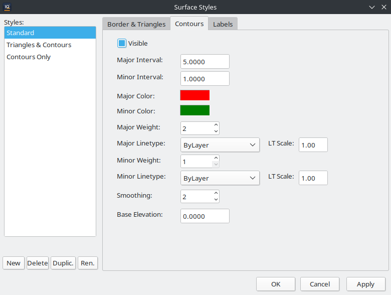
The Surface Style Editor dialog.
3.11.7. Table Styles
Format › Table Styles… opens the Table Style Manager. Select a style and click Edit to open the Table Style Editor, or click New to create a style from scratch.
Three built-in presets are provided:
Preset |
Description |
|---|---|
Standard |
General-purpose table with a bold title row, a header row, and plain data rows. |
Schedule |
Optimised for quantity schedules — compact data rows with alternating fill colours for readability. |
Legend |
Suitable for map legends — no title row, header row uses a coloured background. |
The editor organises settings into three row categories — Title, Header, and Data — each with its own tab. Per-category properties:
Property |
Description |
|---|---|
Text Height |
Height of cell text in world units. |
Alignment |
Horizontal alignment: Left, Centre, or Right. |
Bold / Italic |
Font weight and style for the row category. |
Fill Color |
Background colour of the cells. |
Borders |
Border visibility and weight for horizontal / vertical / outline edges. |
Margins |
Horizontal and vertical padding inside each cell. |
The HasTitle and HasHeader checkboxes at the top of the editor control which row categories appear in new tables that use the style. Unchecking HasTitle, for example, omits the title row entirely.
3.11.8. Multiline Styles (Ctrl+Shift+M)
Opens the Multiline Style Editor. A Multiline Style defines how many parallel strands a Multiline entity has, their spacing, colours, and linetypes.
┌─────────────────────────────────────────────────────────────────┐
│  Style name: [Standard              ]   ☐ End Caps              │
│  Elements:                                                       │
│  ┌─────────┬──────────┬──────────────────────────────────────┐  │
│  │ Offset  │ Colour   │ Linetype                             │  │
│  │ +0.500  │ ByLayer  │ ByLayer                              │  │
│  │ -0.500  │ ByLayer  │ ByLayer                              │  │
│  └─────────┴──────────┴──────────────────────────────────────┘  │
│  [Add Element] [Remove Element]                                  │
│  ──────────────────────────────────────────────────────────────  │
│  Preview: ══════════════════════════════════════════════════     │
└─────────────────────────────────────────────────────────────────┘
Field |
Description |
|---|---|
Style name |
Name saved with the drawing. |
End Caps |
When checked, perpendicular lines close the open ends of the multiline. |
Offset |
Distance from the centreline. Use positive and negative values to place strands symmetrically. |
Colour |
Per-strand colour override ( |
Linetype |
Per-strand linetype override. |
Preview strip |
Live preview of the style at the bottom of the dialog. |
3.11.9. Dimension Styles
Format › Dimension Styles… (or type DIMSTYLE in the command line) opens
the Dimension Style Manager. Select a style and click Edit to open
the Dimension Style Editor, or click New to create a style from
scratch.
The editor groups settings into five areas:
Lines — dimension line and extension line colours, weights, offsets, extension amounts, and suppression flags.
Arrows — arrowhead type (Closed Filled, Open, Dot, Arch Tick, None, and others) and size for each end of the dimension line.
Text — text colour, height, gap from the dimension line, vertical placement (centred or above), and font.
Fit — controls what happens when text and arrows do not fit between extension lines.
Primary Units — number format (Decimal, Scientific, Engineering, Architectural, Fractional), decimal precision, angle format, zero suppression, prefix, suffix, scale factor, and rounding.
Use the style dropdown at the top to switch between named styles. Click Reset to revert the current style to its defaults.
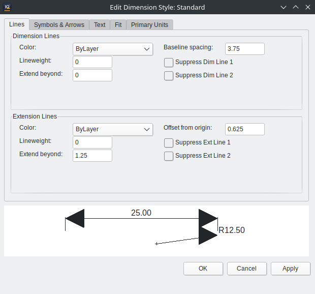
The Dimension Style Editor dialog.
3.11.10. Plot Style Tables (CTB)
Format › Plot Styles… opens the Plot Style Editor. Plot style tables (CTB files) map AutoCAD colour indices to pen settings (colour, weight, screening) for printing and PDF export.
3.11.11. Tunnel Section Line Styles
Format › Tunnel Section Line Styles… opens the Tunnel Section Line Style Editor. A style bundles all visual settings for a tunnel section line entity into one named preset.
Three built-in presets are provided:
Preset |
Description |
|---|---|
Standard |
Measured line with deviation annotations visible, no area hatch. |
Hatched |
Measured line with coloured area hatch (green = overbreak, red = underbreak) between measured and theoretical profiles. |
Simple |
Measured line only, no annotations or hatch. |
The editor organises settings into groups:
Measured Line — colour, weight, linetype, spline interpolation settings.
Deviation Lines — visibility, weight, linetype, overbreak/underbreak colours.
Area Hatch — visibility, pattern, scale, angle, alpha, separate overbreak/underbreak hatch colours.
Center Marker — visibility, colour, size.
DR Display — orientation (Auto/Inside/Outside), alignment (Horizontal/Vertical/Aligned), display mode (All, None, Extremes, Zone Extremes, Threshold, Interval, Smart), threshold and interval values.
DR Label Style — reference to a named civil label style for the deviation labels.
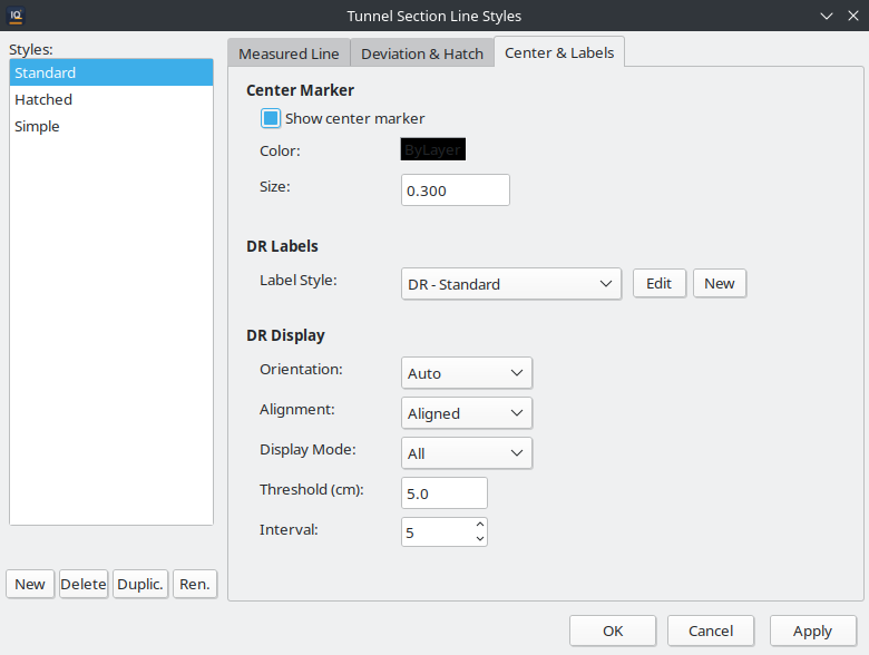
The Tunnel Section Line Style Editor.
3.11.12. Parcel Styles
Format › Parcel Styles… opens the Parcel Style Editor. A parcel style controls the visual display of parcel boundary polygons, fills, and segment labels.
Five built-in presets are provided:
Preset |
Description |
|---|---|
Standard |
Boundary line only, no fill or segment labels. |
Property |
Boundary with semi-transparent fill and bearing/distance labels on each boundary segment. |
Easement |
Dashed boundary with a light fill pattern for restricted zones. |
ROW |
Right-of-way style with a heavy boundary and cross-hatch fill. |
Empty |
All components hidden ( |
The BoundaryVisible flag in the Boundary settings group controls whether the parcel outline is drawn. Setting it to False (as the Empty style does) hides the boundary entirely while preserving the parcel data.
The editor organises settings into groups:
Boundary — visibility, colour, weight, linetype.
Fill — visibility, fill colour, transparency.
Labels — visibility, text height, colour, bearing format (Bearing, South Azimuth, North Azimuth, Angle), distance display, segment label text properties; a Vertex Labels group adds a Vertex Names Visible checkbox plus a label-style dropdown that picks which civil label style renders the corner names (see Parcel Vertex Names). The built-in Property style has Vertex Names Visible checked by default — pair it with the built-in Parcel Vertex civil label style to display the names.
3.11.13. Alignment Styles
Format › Alignment Styles… opens the Alignment Style Editor. An alignment style controls the display of horizontal alignment entities: centerline, station ticks, PI markers, and direction arrows.
Four built-in presets are provided:
Preset |
Description |
|---|---|
Standard |
Centreline + station ticks + PI markers + direction arrows. |
Centerline Only |
Centreline visible; ticks, PI markers, and arrows hidden. |
Design Phase |
Centreline as CENTER linetype, PI details and PI lines visible, full labels. |
Empty |
All components hidden. Use to suppress an alignment from display without deleting it. |
Property Group |
Settings |
|---|---|
Centerline |
Visibility, colour, weight, linetype, linetype scale. |
Station Ticks |
Visibility, major/minor tick intervals, tick lengths, colour, weight, linetype. |
PI Markers |
Visibility, colour, marker size. |
Direction Arrows |
Visibility, interval, colour, arrow size. |
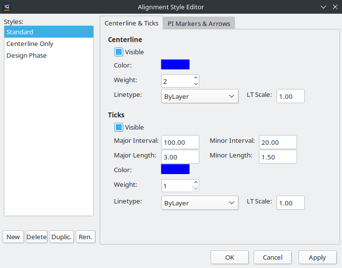
The Alignment Style Editor.
3.11.14. Alignment Label Styles
Format › Alignment Label Styles… opens the Alignment Label Style Editor. Label styles control the text annotations shown along an alignment:
Property Group |
Settings |
|---|---|
Text |
Text style name, text height, text colour. |
Station Labels |
Major/minor station label visibility, label offset from centerline. |
PI Labels |
Visibility, which data to show (radius, spiral length, tangent length, deflection angle), label offset. |
Curve Data Labels |
Visibility, which data to show (arc length, chord length, degree of curve), label offset. |
Other |
Alignment name label visibility, station equation labels. |
3.11.15. Civil Label Styles
Format › Civil Label Styles… opens the Civil Label Style Editor. This is a unified label style system shared by all civil entities: survey points, surfaces (contour labels), alignments, tunnel deviations, and parcels.
A civil label style defines:
Components — a list of label rows, each specifying a content type (e.g. point number, elevation, station, contour elevation, deviation), prefix, suffix, and number format.
Font — text style, height, colour, bold/italic.
Placement — anchor mode (point, linear, or area), offset, rotation, background mask settings.
Built-in presets cover common use cases for points, contours, alignments, tunnel deviations, and parcels. The label style editor groups styles by category: Point, Contour, Spot Elevation, Station, PI, Tunnel (DR), and Parcel.
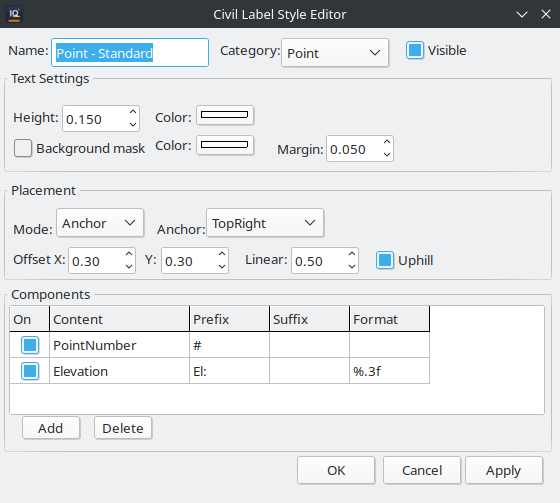
The Civil Label Style Editor.
3.11.16. Unified Style Managers
IQcad provides two unified style manager windows that consolidate all style editors into a single dialog, eliminating the need to open individual style editors from separate ribbon buttons.
CAD Style Manager (Format > CAD Style Manager…) — a single window with a category tree on the left and the corresponding embedded editor on the right. Categories include:
Text Styles
Dimension Styles
Table Styles
Multiline Styles
Point Styles (CAD point marker shape)
Plot Style Tables (CTB)
Civil Style Manager (Civil > Styles or Format > Civil Style Manager…) — a single window for all civil-specific styles:
Point Styles (survey point marker + label)
Surface Styles
Tunnel Section Line Styles
Alignment Styles
Parcel Styles
Civil Label Styles
Both managers support creating, editing, duplicating, and deleting styles. Select a category in the tree, then use the style list and editor panel on the right. Styles are saved with the drawing.
The individual Format menu entries (e.g., Format > Text Style…, Format > Surface Styles…) remain available as shortcuts that open the corresponding section directly.