
Knowledge base · Surfaces
Set how a surface is drawn
Every control in the surface style editor — border, triangles, contours, labels, breaklines, elevation bands and draw order.
A surface style is the named set of drawing settings for one TIN. It covers the border, the triangles, the TIN points, the contours, the labels, the breaklines, the elevation bands, and the order those parts are drawn. The surface stores the style name. An edit to a style is picked up by every surface that uses that name.
Build the surface first. Put survey points in a group and build a surface is the usual way in.
Open the editor
The figures below are the Civil Style Manager, on the Standard style.
- On the Civil ribbon, click Styles.
- In the list on the left, click Surface Styles.
Civil › Civil Style Manager... opens the same window. The left-hand list also holds point styles, alignment styles, label styles and the other civil styles. This article is the Surface Styles page.
Three other commands open the surface editor on its own, with OK, Cancel and Apply:
- Civil › Styles › Surface Styles...
SURFACESTYLE(aliasSUS)- Right-click the surface in the Civil Toolspace and choose Surface Style.... The list opens on the style that surface already uses.
Apply writes the styles into the drawing and rebuilds every surface. In the Civil Style Manager, Close writes them as well. There is no discard button on that window. In the standalone editor, OK writes and closes, and Cancel throws the edits away.
The list of styles
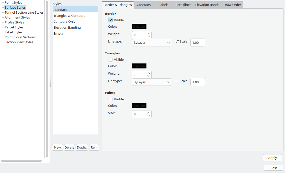
A new drawing has five styles.
- Standard shows the border, the contours, the contour labels, the spot elevations and the breaklines. Triangles, TIN points and elevation bands are off. The figures on this page are Standard.
- Triangles & Contours is Standard with the triangles turned on. The border stays on.
- Contours Only hides the border. Contours, labels and breaklines stay on.
- Elevation Banding keeps the contours, turns elevation bands on, and paints each contour from the band table.
- Empty hides the border, the triangles, the contours, the points, the elevation bands, the contour labels and the spot elevations. Breaklines stay visible, so a surface you have suppressed can still show its breaklines.
The buttons under the list:
- New asks for a name. The suggestion is
Styleand a number. The new style starts with the same settings as a fresh Standard. - Duplic. copies the selected style. The copy is named with
Copyon the end. Use a copy when one surface should look different from the others. Two surfaces that share a name share every later edit. - Ren. asks for a new name. Standard cannot be renamed.
- Delete asks you to confirm. Standard cannot be deleted, and neither can the last style left in the list.
The styles are saved with the drawing.
Border and triangles
The first tab draws the outline, the TIN edges and the TIN vertices.
Border
The border is the outline of the surface. Visible shows it. Color, Weight, Linetype and LT Scale set the pen.
On Standard the border is visible, the colour is ByLayer, the weight is 2, the linetype is ByLayer and the scale is 1.00. Weight runs from 1 to 20.
Triangles
These are the edges of the TIN. The same five controls apply. On Standard they are hidden, ByLayer, weight 1, linetype ByLayer, scale 1.00.
Points
These are the TIN vertices, drawn as small filled markers. They are not the survey-point markers, and they are not the spot-elevation crosses on the Labels tab.
On Standard they are hidden, ByLayer, size 3. Size is in screen pixels and runs from 1 to 20.
Colour, linetype and ByLayer
Click a colour swatch. The choice is ByLayer, Pick Color..., or Cancel.
ByLayer follows the component layer of that part. When the civil object layers are on, the default layers are C-TOPO-BNDY (yellow) for the border, C-TOPO-TRIA (grey) for the triangles, C-TOPO-MAJR (brown) for major contours, C-TOPO-MINR (dark green) for minor contours, and C-TOPO-PNTS (gold) for the TIN points. A colour you pick on the swatch replaces that layer colour for the style.
The linetype list is ByLayer, then every linetype in the drawing. LT Scale stretches the dash pattern. A value that is not a number is stored as 1.
Contours
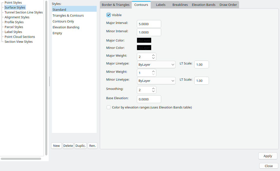
Visible draws the contour lines. It is on for Standard.
Major Interval and Minor Interval are elevations, in drawing units. A contour is generated at every minor step. A contour is major when its elevation lands on the major step, counted from Base Elevation. Major lines use the major colour, weight and linetype. The rest use the minor pen.
On Standard the major interval is 5, the minor interval is 1, and the base is 0. Contours then fall on whole units, and every fifth contour is major. Move the base to shift the whole set. A base of 0.5 with the same intervals puts contours on 0.5, 1.5, 2.5, and the majors on 0.5, 5.5, 10.5.
Smoothing runs from 0 to 5. Zero keeps the straight segments that come off the triangles. Each higher step rounds the corners once. Standard uses 2.
Color by elevation ranges (uses Elevation Bands table) is off on Standard. Turn it on to paint each contour with the colour of the band its elevation falls in, instead of the major and minor colours. The band table has to contain rows. The Elevation Banding style turns this box on.
On Standard both colours are ByLayer, the major weight is 2, the minor weight is 1, both linetypes are ByLayer, and both scales are 1.00.
Changing the interval, the base or the smoothing rebuilds the contour lines.
Labels
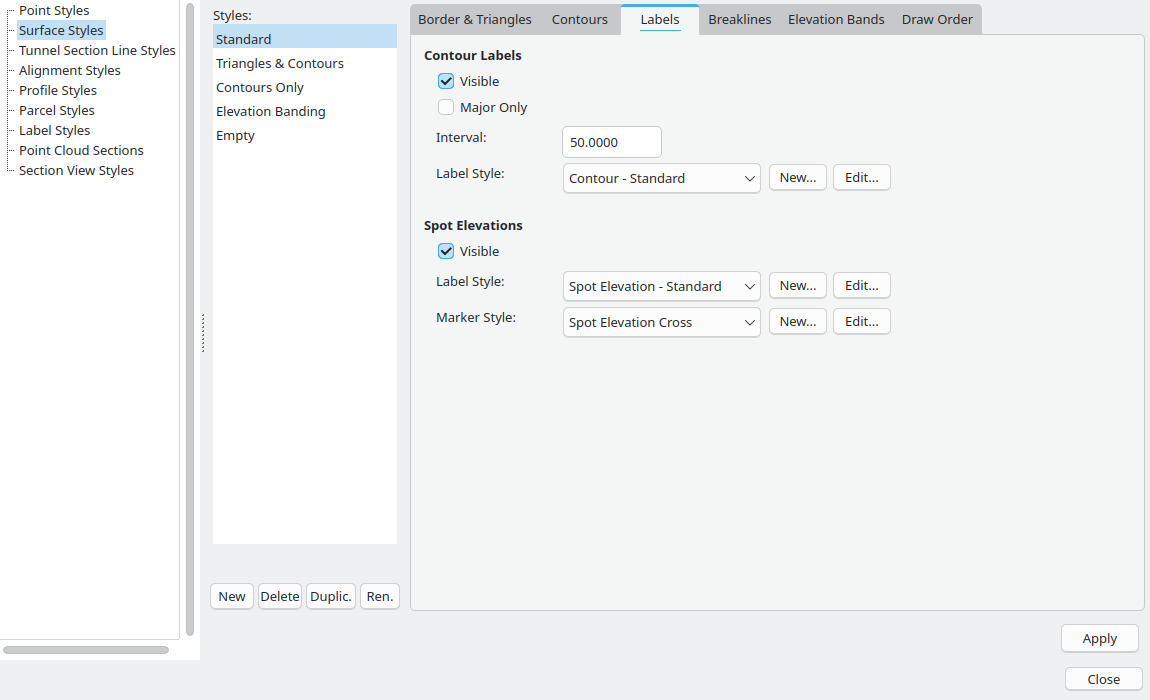
Contour labels
Visible places elevation text along the contours. It is on for Standard.
Interval is a distance along the contour, in drawing units. The first label sits half an interval from the start of the line. Further labels follow at each interval. A label is left out when another label is already closer than half that interval. Standard uses 50.
Major Only labels the major contours and skips the minor ones. It is off on Standard, so both are labelled.
Label Style names a civil label style. Standard uses Contour - Standard. That style prints the elevation with one decimal, aligns the text with the contour, turns it so it reads uphill, and uses a text height of 2.0 mm.
New... asks for a name, creates a label style in the Surface category, and opens the label editor. Edit... opens the style named in the list. The list only offers label styles in the Surface category.
Spot elevations
These are the labels from the Spot Elevation command, SPOTELEV (alias SE). They are a marker plus a text at a point you clicked on the surface. They are not the TIN vertex markers on the first tab.
Visible is on for Standard. Label Style is Spot Elevation - Standard, which prints the elevation with two decimals at a text height of 1.5 mm. Marker Style is Spot Elevation Cross.
New... and Edit... beside the label open the label editor. Beside the marker they open the point-style editor. A new marker starts as a cross.
Breaklines
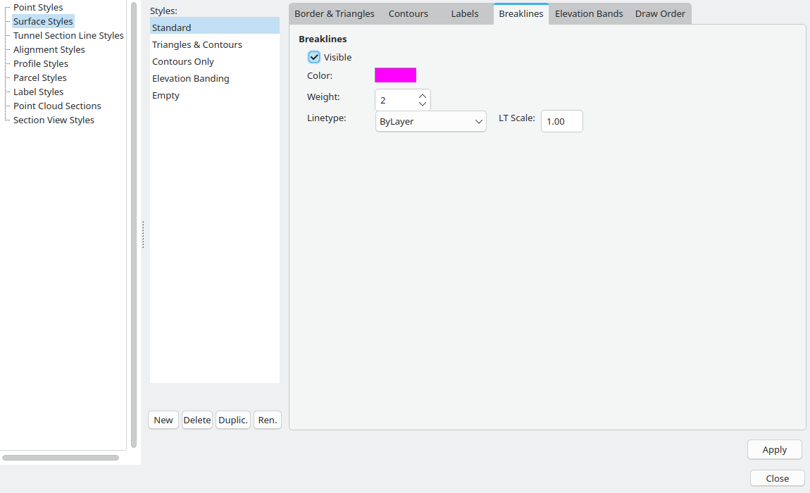
This tab only draws breaklines that are already in the surface. Make a TIN follow a breakline is how a breakline gets into the TIN.
Visible, Color, Weight, Linetype and LT Scale are the same kind of pen as the border. On Standard the lines are visible, magenta, weight 2, linetype ByLayer, scale 1.00. The magenta is a colour on the style, so it does not follow the layer the way a ByLayer swatch does.
The component layer suffix is BRKL, so the layer is C-TOPO-BRKL when the civil object layers are on. A colour picked here is what you see.
Elevation bands
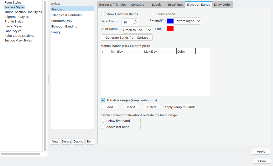
An elevation band paints the TIN by height. Each vertex takes the colour of the band that contains its elevation, and the fill blends across the triangle.
Show Elevation Bands is the master switch. On the Standard style in these figures it is clear, and so is Show Legend. Nothing is filled until the table has rows and the bands are shown.
Band Count runs from 2 to 100. Standard shows 10. Changing the number does not rebuild the table by itself. Generate Bands from Surface and Apply Ramp to Bands read it.
Color Ramp is one of:
- Green to Red — low ground green, high ground red.
- Blue to Red — low ground blue, high ground red.
- Grayscale — low ground black, high ground white.
- Custom — a blend from the Start swatch to the End swatch.
The three named ramps ignore Start and End. On this tab the Start swatch is blue and the End swatch is red because those are the swatches' own colours, not because Green to Red uses them. Click a swatch to open the colour dialog. These two swatches have no ByLayer choice.
Legend Corner is Top Left, Top Right, Bottom Left or Bottom Right. Standard shows Bottom Right. The label sits against the Start swatch. The legend is a stack of colour boxes and elevation ranges, highest at the top, drawn on the screen in that corner. It appears only when Show Legend is on, the table has at least one row, and either the bands are shown or Color by elevation ranges is on. A style can ask for a legend and still draw none until the table has rows.
Generate bands from a surface
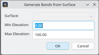
Generate Bands from Surface opens a small dialog.
- Surface lists every surface in the drawing. A surface that already uses the style you are editing is selected. Otherwise the first surface is selected. Changing the surface fills Min Elevation and Max Elevation from that surface. You can type other numbers before generating.
- OK builds the bands. Cancel leaves the style alone.
- Both boxes have to be numbers, and the maximum has to be greater than the minimum.
- When the drawing has no surface, the list is disabled and the boxes start at 0 and 100. That is the dialog in the figure. Type the range you want.
OK splits the range into Band Count equal bands and turns Show Elevation Bands on. Ten bands from 100 to 110 are ten steps of 1. Leave the surface's own minimum and maximum when the colours should cover the whole TIN.
The band table
The columns are #, Min Elev, Max Elev and Color. Click a number cell and type. Click Color to open the colour dialog for that row.
Auto-link ranges (keep contiguous) is on. Editing a row's maximum writes that number into the next row's minimum. Editing a minimum writes it into the previous row's maximum. Turn it off when the ranges are allowed to leave a gap.
- Add appends a row. The row starts where the last row ends and is one unit wide, in yellow. On an empty table the first row is 0 to 1.
- Insert splits the selected row at its midpoint. The new row is aqua. With auto-link on, the following row's minimum moves up to that midpoint.
- Delete removes the selected row.
- Apply Ramp to Bands recolours the existing rows from the ramp. It does not change the elevations, and it does nothing while the table is empty. A named ramp ignores Start and End. Custom uses them.
The rows are stored in elevation order. A band covers from its minimum up to, and not including, its maximum.
Outside the table
Below first band and Above last band are the colours for elevations outside the table. Both are clear on the Standard style in the figures. The swatch beside each box is used only while the box is ticked. On a new style that colour is grey.
While a box is clear, ground below the first band keeps the first band's colour, and ground above the last band keeps the last band's colour.
Draw order
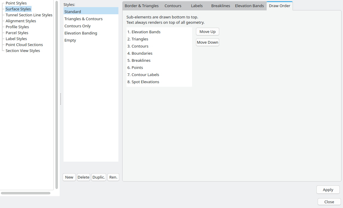
The tab says it: sub-elements are drawn bottom to top, and text always renders on top of all geometry.
Read the list from the top as back to front. Item 1 is drawn first and sits underneath. The last item is drawn last and sits on top. Move Up sends the selected line further back. Move Down brings it forward.
Standard order:
- Elevation Bands
- Triangles
- Contours
- Boundaries
- Breaklines
- Points
- Contour Labels
- Spot Elevations
Contour labels and spot elevations stay above the geometry even if you move them up the list.
This list is the order inside one surface. The order between surfaces, parcels, alignments and points is a different list, on the Draw Order tab of Civil › Civil Settings....
Put the style on a surface
- Select the surface.
- In the Object Inspector, set StyleName.
The surface rebuilds with that style. Apply in the editor, and Close on the Civil Style Manager, rebuild every surface from the styles as they stand.